

Modern data centers and today’s underlying network infrastructure will continue to evolve to meet the requirements of leading technologies. As organizations look at ways to cut costs, reduce their environmental impact and converge traditionally disparate operational and IT systems, data centers are chasing to keep pace with assurance of deployment stability and uptime expected. We speak to Andrew Froehlich, President of West Gate Networks, and Lisa Schwartz, Director of Product Marketing at AEM, on the nuances of testing and troubleshooting cabling in data center environments and why it is important to realize that testing needs have also evolved to keep pace.

What are the different types of data centers from a cabling perspective?
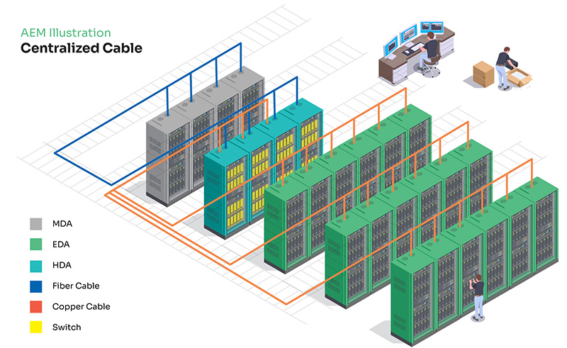
Firstly, there is the Centralized Cable. Small data centers or those that formed in an unstructured manner, such as pre-existing data centers where technologies were adopted after the initial design that might include support of IoT initiatives, Single Pair Ethernet, or adoption of Hyper Converged Infrastructure (HCI), are just a few examples.
These types of data centers will centralize cabling and patch panels into a consolidated rack or group of racks. Servers and storage located in racks surrounding the patch panels can connect with relatively short patch cables. However, the further away servers and other network-connected devices are, the longer the patch cables need to be. It’s often the case that cable management becomes disorganized and sloppy as the number and lengths of cabling required to connect data center devices becomes significant in such a small and centralized section of the server room.

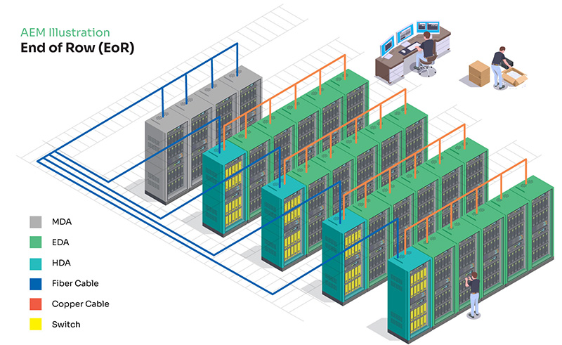
Secondly, there is End-of-Row Cabling. Looking to alleviate much of the cabling congestion of a centralized patch panel design, larger legacy data centers (DC) are known to utilize distributed cable patch panels and switching/ fiber channel switch hardware into several locations within the DC facility. In many cases, each DC row will have their own rack that is designated for cabling and patch panels.
This is known as an ‘End-of-Row’. All devices mounted in this row connect to the DC network at the End-of-Row distribution point. While this design does help to disperse the density of patch cables to multiple locations, the layout can still suffer from cable congestion in DC that have racks stacked full of equipment that must be connected.
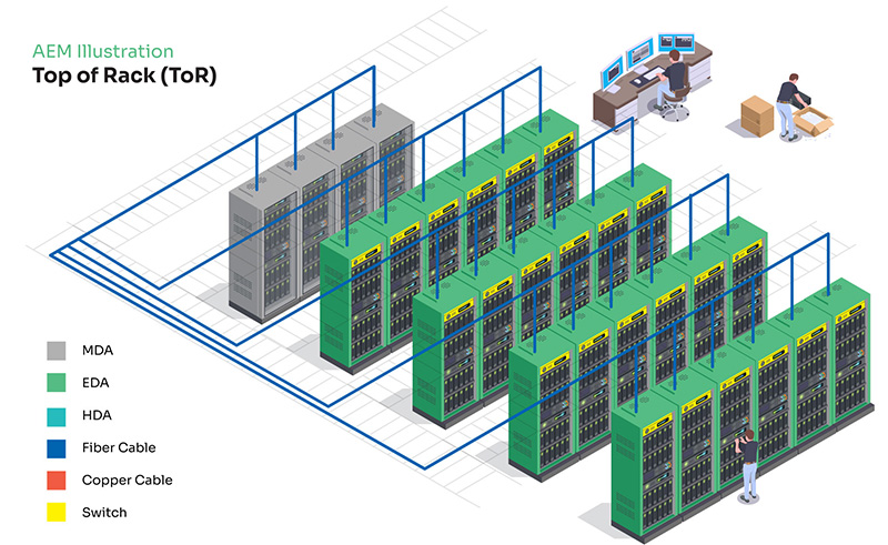
Lastly, we have Top-of-Rack. The Top-of-Rack design is newer than the End-of-Row and centralized architectures. Using this plant blueprint, the cabling termination points become distributed even further. Each equipment rack in the DC is installed with an Ethernet and/or fiber channel switch at the top.
Any equipment installed in the rack is in close proximity to network switch ports. This keeps patch cable lengths short, uniform and under control. Each Top-of-Rack switch then uses high speed uplinks to interconnect all distributed switches in the facility to one or more racks of aggregation switches. While this model indeed reduces cable management issues inherent in other designs, it increases the amount of switch hardware required and can complicate cable troubleshooting efforts as data must now pass through multiple cables and network hardware.
While this model indeed reduces cable management issues inherent in other designs, it increases the amount of switch hardware required and can complicate cable troubleshooting efforts as data must pass now through multiple cables and network hardware.
Can you tell us what some of the network connectivity challenges are within these different types of DC and how AEM can help test and/or resolve those issues?
Regardless of whether your DC cabling is run by in-house staff or a professional third-party cabling crew, mistakes do happen. Problems with existing cabling may go unnoticed for weeks, months or years for several reasons. For example, it’s possible that the cabling was never put into production until recently. Or perhaps upgraded network hardware now requires the cabling to support higher transport speeds.
Another factor is buildout to support emerging technologies, such as those discussed earlier in this document and might include Single Pair Ethernet (SPE). Finally, cabling may need to transport power over twisted pair cabling for the first time. Regardless, the precise location of the cabling mistake will lead to far faster problem resolutions. It’s not uncommon for cabling to become bent, stretched or kinked beyond manufacturer specifications.
Enterprise-grade cable test equipment can often not only identify that there indeed is a performance problem – but can also pinpoint the precise location of where the fault has occurred on the cable. Knowing this can significantly reduce the amount of time required to fix this issue – as well as point to other cables in a bundle that may also have been damaged due to improper installation techniques.
Can you tell us more about the testing of the cabling within the data center environment?
When it comes to choosing the right test tool for your DC, there are a couple of factors to consider. Test tools can be purchased individually or as a broad-based multifunction test solution. While some may opt to purchase individual tools on an as-needed basis, understand that the cost of each tool will eventually surpass the cost of a multifunction tester purchased up front.
Additionally, multifunction testers leverage the same user interface making training an easier endeavour. Finally, understand that some multifunction test units are modular by design. This means that test functions can be upgraded over time and new test capabilities – both from a hardware and software perspective – can be upgraded to extend the usefulness of the tester over time.
Having the right toolset could save thousands of dollars from lost productivity from both the users themselves as well as those responsible for overseeing network infrastructure and DC support.
What should DCs understand about testing and troubleshooting within their Cable Plants?
Given today’s competitive landscape, businesses must always be on the lookout for ways to improve DC performance and reliability. As legacy DC hardware and software gets swapped out with modern technologies with the goal of better application performance and stability, one must not forget about the impact this has on the existing DC copper and fiber plants.
It’s not uncommon, for example, for a brand-new technology to be implemented within a DC only to have it be plagued by connectivity issues, lower than expected speeds and other inconsistencies caused by cabling. Additionally, DC trends that leverage power over Ethernet (PoE) for various IoT purposes within a DC are also on the rise. Common examples include surveillance cameras, LAN-connected door controllers, temperature/humidity sensors and PoE lighting.
These additions are creating a much higher demand for PoE within the DC than ever before. Significant increases in the number of PoE connections can cause several unforeseen problems – especially when twisted-pair cable plants were not designed with PoE delivery in mind. The distribution of electricity over copper cables increases heat and electromagnetic interference that can impact individual cables as well as cross cable interference with other twisted-pair runs within a cable bundle, and power delivery through low-voltage copper.
Keep in mind that there’s often more cabling in the DC compared to any other part of an organization’s network. It should also come as no surprise that the DC is the heart of every enterprise network. Thus, a great deal of testing and troubleshooting will take place in this demanding location.
Can you tell us about the need for documentation and reporting of connectivity and cabling performance be it copper or fiber?
Previously, it was not uncommon for the cable contractor to install a cabling system, and not provide the test results to the network owner. However, more companies now require proof that tests were run to validate and certify the cabling, providing assurance to the end-users of the installation quality, and that the cabling can support intended smart building applications.
This documentation also protects the installer, who can return to the reports as a troubleshooting aid, should they be called back to the site to resolve an issue. The installer can see how the cable performed as they left it, verses how it is performing now.
There is the traditional twisted pair copper cable certification report, as well as fiber optic. From the installer’s perspective, if they were to provide a warranty or expect warranty support from the cable manufacturer, those printed reports are critical, and required by the cable manufacturer. The network owner can also refer to this report if end devices are not functioning correctly, by being able to review the performance of the cable, and that it passed certification testing at the time of install. If the network owner has the necessary test equipment with the ability to certify, they can test and compare to the most recent performance of the cable.
Beyond reporting on the cabling itself, during the implementation phase, having test equipment with the added ability to troubleshoot and attain printed reports for wired and wireless network connectivity and performance is invaluable for network owners to have at their fingertips, as the data, such as switch slot/port/VLAN or AP signal strength, is critical to support moves, adds and changes and troubleshooting within systems.
Click below to share this article